Demonstrator - Joy-IT - Explorer 700
Overview
The Explorer 700 multifunctional board is a allrounder. It has many usable interfaces and interesting expansions.
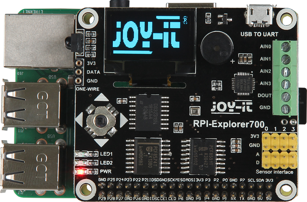
https://joy-it.net/de/products/RB-Explorer700
Pinout
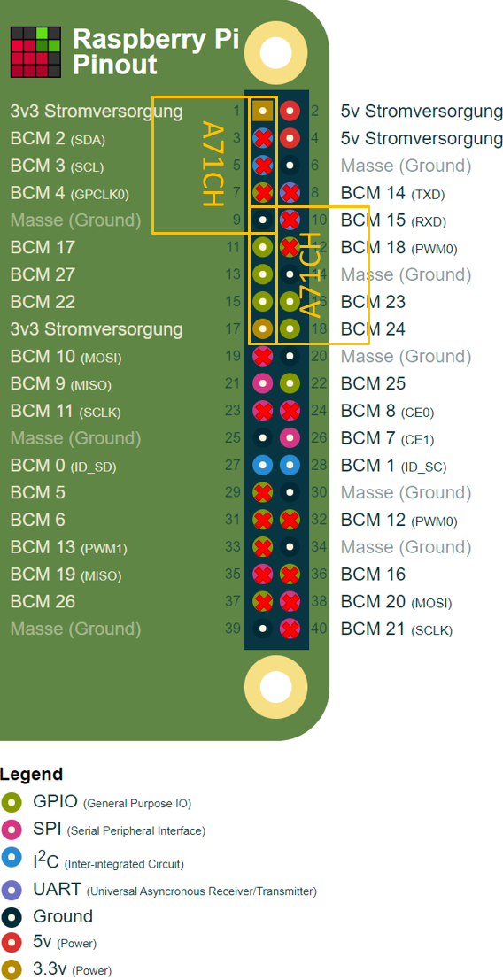
Pins with a rec cross are data pins in use by the Explorer 700.
Because the A71CH needs the I²C bit-banging interface, the Explorer 700 would also have to use it.
But because every GPIO pin can be used for the I²C bit-banging interface it can be moved.
Conveniently the pins 9, 11, 13, 15 and 17 also provide 3,3 V voltage and ground as well as 3 GPIOs in a row.
The Simplecion A71CH would just have to be moved rotated and the regular hardware I²C pins can be used for the Explorer 700.
https://joy-it.net/files/files/Produkte/RB-Explorer700/RB-Explorer700-Manual-20200623.pdf
I²C devices
Name | Address | Description |
|---|---|---|
PCF8574 | 0x20 | Remote 8-Bit I/O Expander |
PCF8591 | 0x48 | 8-bit A/D and D/A converter |
DS3231 | 0x68 | Accurate Real-time clock |
BMP280 | 0x76 | Digital pressure sensor |
Coincidentally the PCF85918-bit A/D and D/A converter ist using the same I²C address (0x48) as the the Simplexion A71CH demo board.
Neither of the addresses can be changed because they depend on the wiring, so it would have been problematic if they shared the same I²C bus.
1-Wire devices
Name | Pin | Description |
|---|---|---|
DS18B20 | BCM 4 | Digital Thermometer |
SPI devices
Name | CE Pin | Description |
|---|---|---|
SSD1306 | BCM 8 (CE0) | 128 x 64 Dot Matrix OLED/PLED Segment/Common Driver with Controller |
Code
Multiple archives of example code from Joy-IT can be found on their website.
- The fist archive only includes examples for a few peripherals only for Python.
Explorer-700 Beispielcodes.zip
https://joy-it.net/files/files/Produkte/RB-Explorer700/Explorer-700%20Beispielcodes.zip
https://joy-it.net/de/products/RB-Explorer700
- The second archive includes examples for all the sensor for Pyhton and the wiringPi and bcm2835 C libraries.
Explorer700-1.zip
http://anleitung.joy-it.net/wp-content/uploads/2016/12/Explorer700-1.zip
http://anleitung.joy-it.net/?goods=explorer-700
The bcm2835 C library has been chosen because wiringPi is deprecated now and the maintainer even deleted his GIT repository where BitBake is trying to get the source code from.
http://wiringpi.com/wiringpi-deprecated/
SSD1306 OLED display
Joy-IT demo
The demo application from Joy-IT for the SSD1306 OLED display is using the bcm2835 C library, which uses direct memory access to control the SPI interface.
It is not required to enable the SPI device interface for user space, but the application needs root privileges for direct memory access.
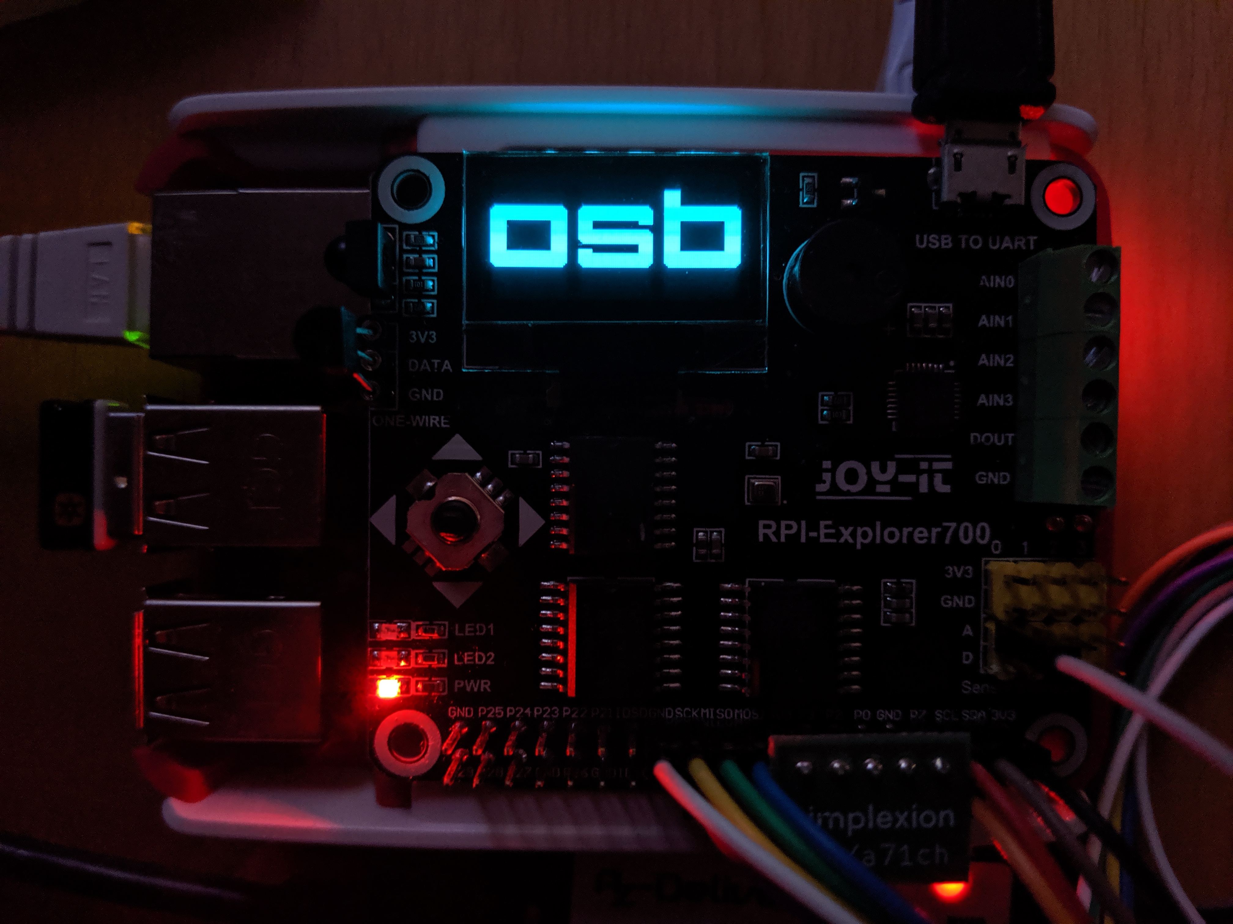
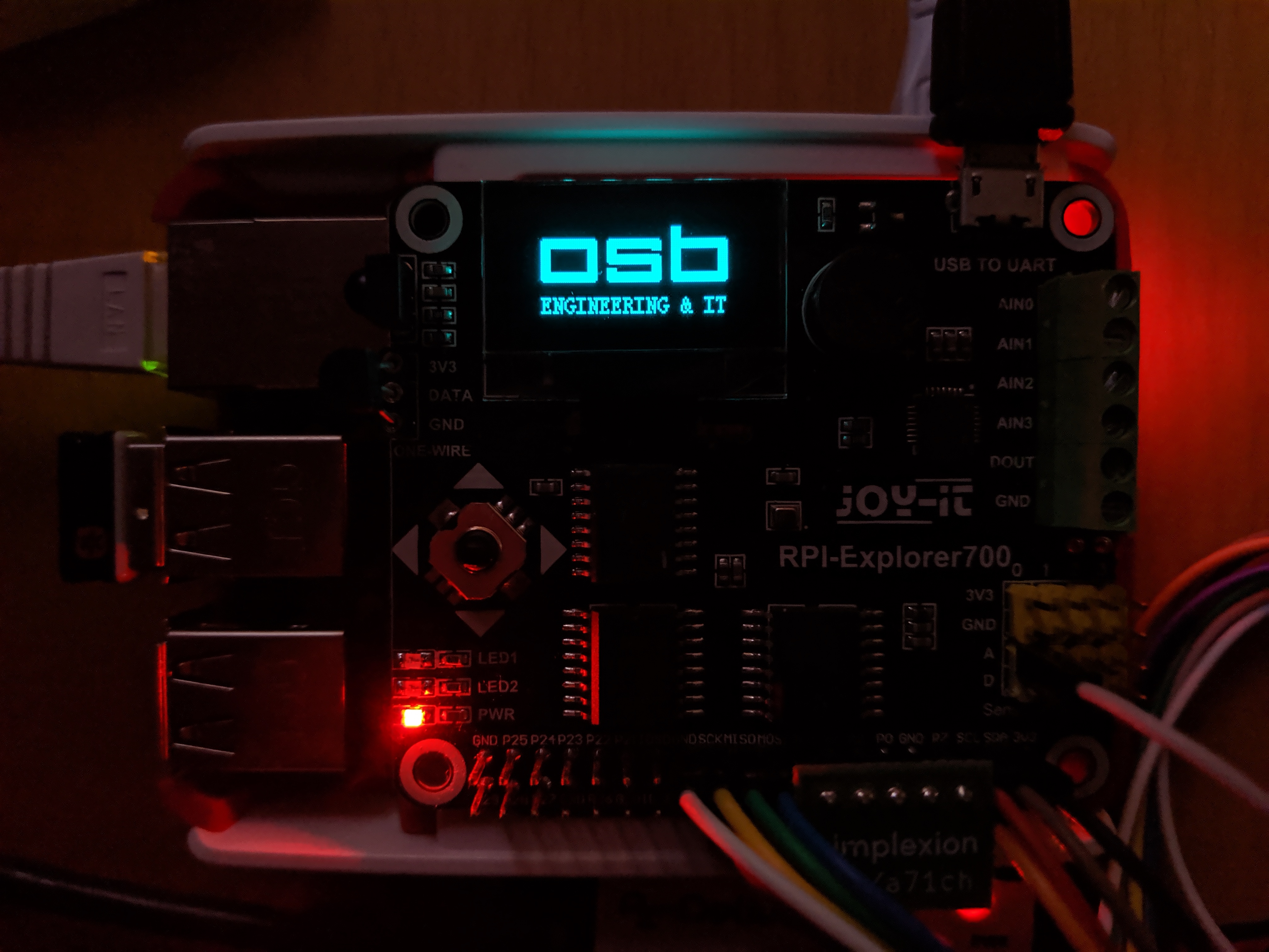
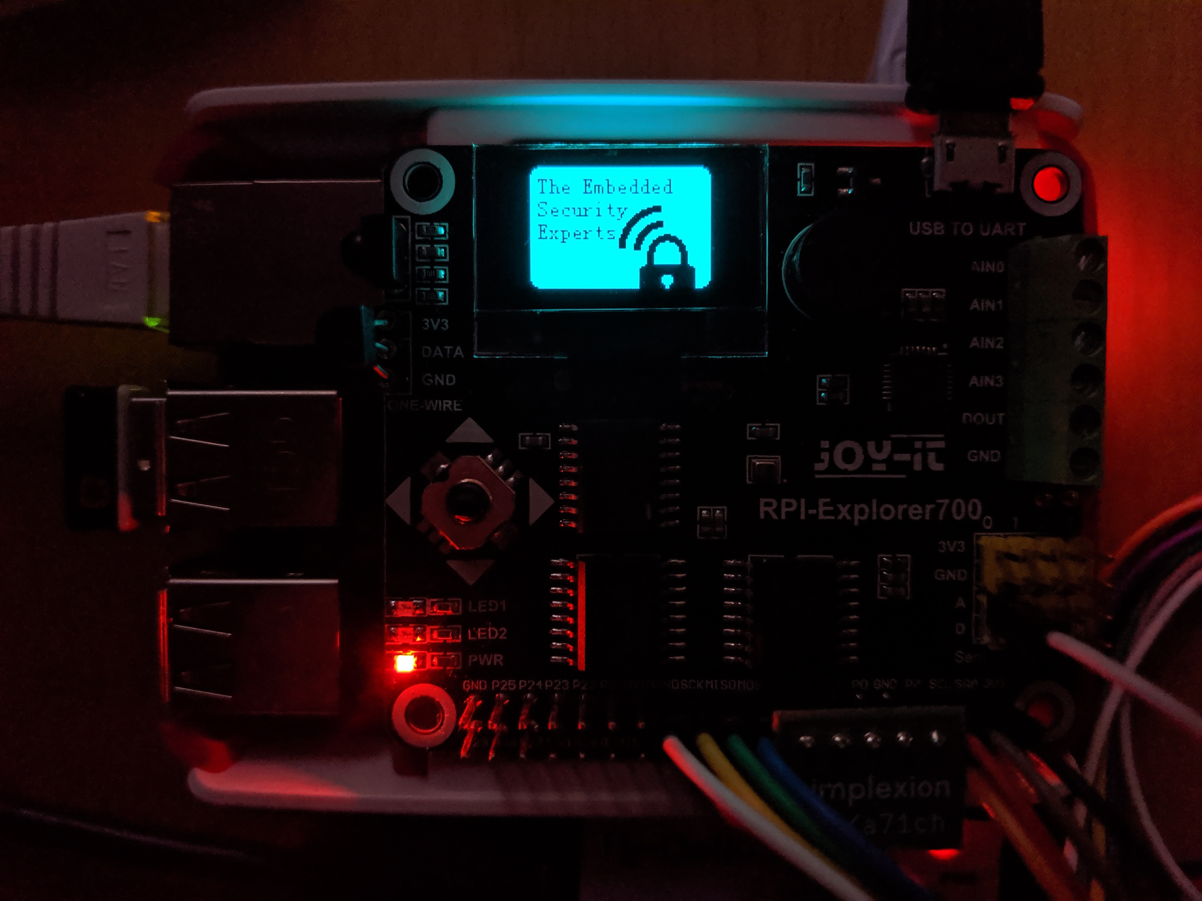
A demo application called oled-demo has been added to the demonstrator image that is displaying OSB and ESEC logos.
logos.zip
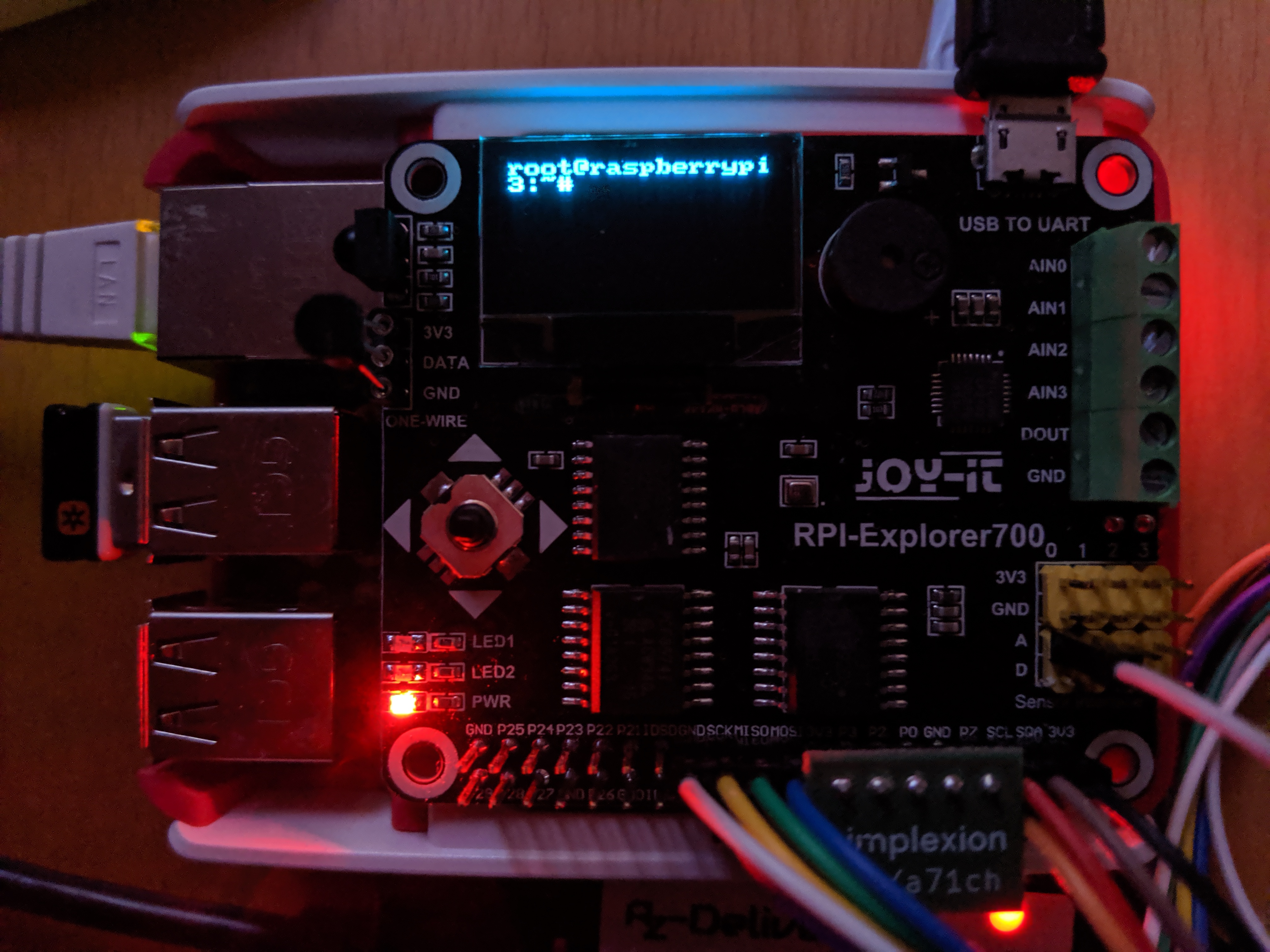
Login console
There is also support for displaying a console on the SSD1306 OLED display.
https://github.com/raspberrypi/firmware/blob/542aceb30364db3ce87d532ea90451f46bbb84e9/boot/overlays/README#L2588
The display can only fit at most 8 lines with 16 characters per line.
Tmux
The oled display will lanuch a tmux session instead of showing a login prompt after boot.
You can attach to this tmux session by executing tmux a.
You can detach from the session by pressing Ctrl + B and then D.
Everything that has been launched from inside the session will still be shown on the oled screen after detaching.
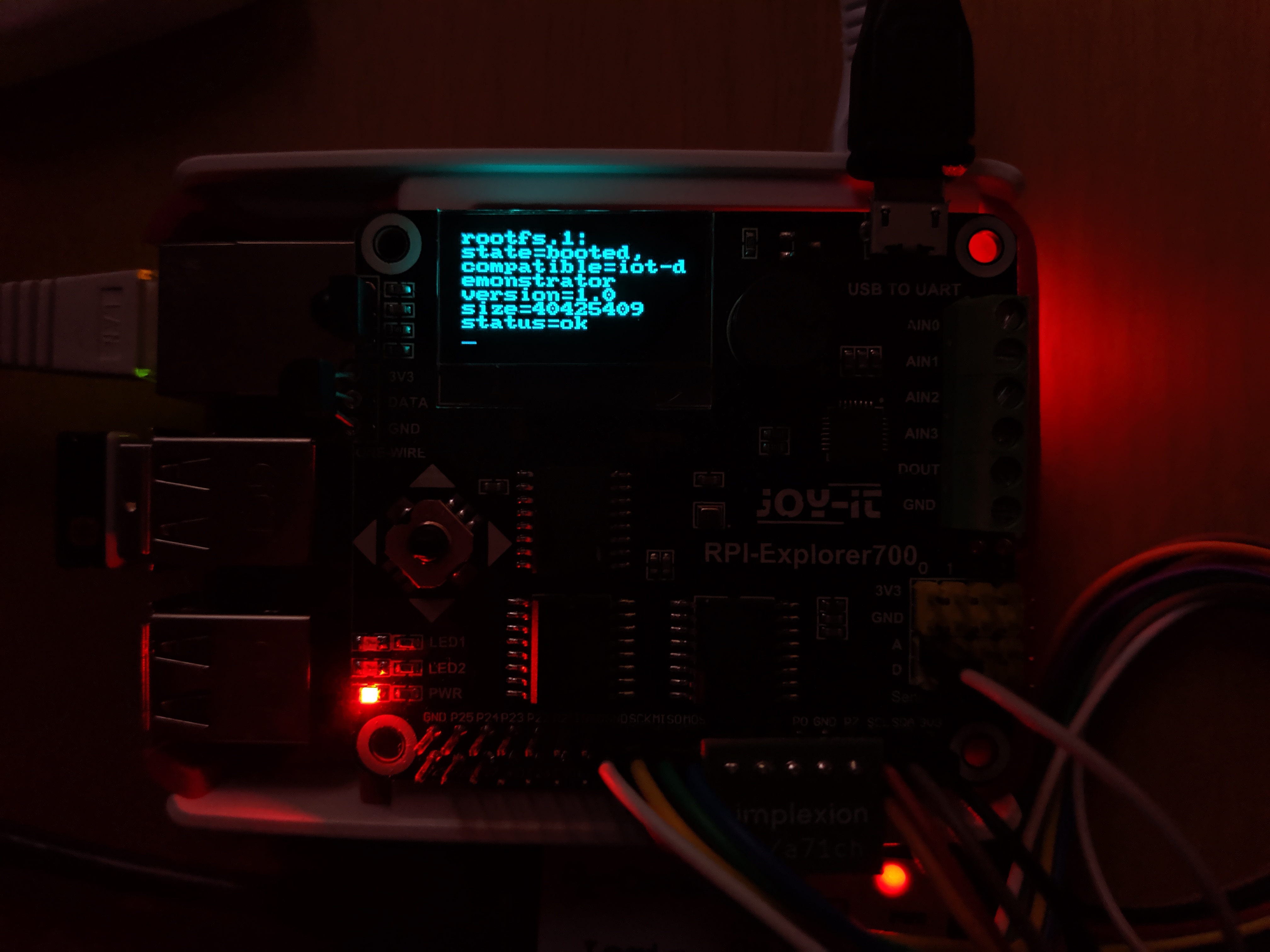
Images with framebuffer
By using a tool called fbi, images can be shown via the framebuffer instead of the console using the following command.
# fbi -T 1 --noverbose image.pngYou habe to execute this command from outside the tmux session of the oled display.
The image will continue to be shown even after the fbi command returns.
To display the console again you can kill the session by executing tmux kill-session from outside the session or press Ctrl + D from inside the session.
This will relaunch a new tmux session that will be displayed on the oled display again.
Photos
Videos
DS18B20 Digital Thermometer
The DS18B20 Digital Thermometer is connected via 1-Wire.
After enabling 1-Wire temperature sensor support to the kernel the measured temperature in m°C can be read with the following command.
# cat /sys/devices/w1_bus_master1/28-00000*/w1_slave | grep "t=" | cut -d "=" -f233875GPIOs
LED1
The LED1 of the Explorer 700 is connected to the regular gpio26 of the Raspberry Pi.
Its value can be set using the following commands.
/sys/class/gpio# echo 26 > export/sys/class/gpio# cd gpio26/sys/class/gpio/gpio26# echo out > direction/sys/class/gpio/gpio26# echo 1 > value/sys/class/gpio/gpio26# echo 0 > valueJoystick
The button for pushing the joystick is connected to the regular gpio20 of the Raspberry Pi.
It has been configured to function as a Enter key.
The directions of the joystick are connected to the GPIOs of PCF8574 Remote 8-Bit I/O Expander.
PCF8574 Remote 8-Bit I/O Expander
The PCF8574 Remote 8-Bit I/O Expander adds 8 GPIO to the Raspberry Pi and is connected via I²C at address 0x20.
The PCF8574 is represented by gpiochip496 with 8 GPIOs from gpio496 to gpio503.
The GPIOs can be exported just like the regular GPIOs.
LED2
The LED2 is connected to pin 4 (gpio500) of the PCF8574.
Its value can be set using the following commands.
/sys/class/gpio# echo 500 > export/sys/class/gpio# cd gpio500/sys/class/gpio/gpio500# echo out > direction/sys/class/gpio/gpio500# echo 1 > value/sys/class/gpio/gpio500# echo 0 > valueThe peripherals connected to the PCF8574 seem to be low active.
Upon exporting the will be activated with a value of zero, so the LED2 will light up.
Once a value of 1 is written to the GPIO it will turn off.
Buzzer
The buzzer on the Explorer 700 is connected to pin 7 (gpio503) of the PCF8574.
It can be exported just like the LED2.
Because the pin is low active it will start beeping once the GPIO is set as an output.
/sys/class/gpio# echo 503 > export/sys/class/gpio# cd gpio503/sys/class/gpio/gpio503# echo out > direction; echo 1 > value/sys/class/gpio/gpio503# echo 0 > value; usleep 10000; echo 1 > valueJoystick
The directions of the Joystick on the Explorer 700 are connected to the PCF8574s pins 0 to 3 (gpio496 to gpio499).
Its values can be read by registering the GPIOs as inputs and reading the value sysfs-file.
/sys/class/gpio# for I in $(seq 496 499); do echo $I > export; done/sys/class/gpio# for I in $(seq 496 499); do echo in > gpio$I/direction; done/sys/class/gpio# cd gpio496/sys/class/gpio/gpio496# echo in > direction/sys/class/gpio/gpio496# cat value1For convenience symlinks named after the directions have been created.
# ls -llrwxrwxrwx 1 root root 29 Jul 21 13:22 down -> /sys/class/gpio/gpio498/valuelrwxrwxrwx 1 root root 29 Jul 21 13:22 left -> /sys/class/gpio/gpio496/valuelrwxrwxrwx 1 root root 29 Jul 21 13:22 right -> /sys/class/gpio/gpio499/valuelrwxrwxrwx 1 root root 29 Jul 21 13:22 up -> /sys/class/gpio/gpio497/value# grep . *down:1left:1right:1up:0The inputs are also low active, so they switch from 1 to 0 when they are pressed.
Joystick as key inputs
The directions of the Joystick can also be configured to function as key presses on a keyboard.
Any key can be assigned to the 4 directions and to pushing down the joystick.
One option is to assign the arrow keys to the directions and the enter key to pushing the joystick.
This would allow to navigate two-dimensional menus on the OLED screen and to choose entries.
It would also allow to step trough the shell history using the joystick.
Pressing down the joystick would execute the chosen command.
CCES39645-727
PCF8591 8-bit A/D and D/A converter
The PCF8591 8-bit A/D and D/A converter offers 4 8-bit analog inputs and a 8-bit analog output.
It is connected via I2C at address 0x48.
The 8-bit (0 to 255) measurements of the 4 DACs can be read from sysfs files.
The values that are read are multiplied by 10, so they range from 0 to 2550 in intervals of 10.
/sys/class/hwmon/hwmon1/device# grep . in*in0_input:0in1_input:10in2_input:0in3_input:0The 8-bit value (0 to 255) can be written to a a sysfs file called out0_output.
To enable the signal additionally a 1 haw to be written to the file out0_enable.
The values also have to be multiplied by 10, so they range from 0 to 2550 in intervals of 10.
/sys/class/hwmon/hwmon1/device# echo 1280 > out0_output/sys/class/hwmon/hwmon1/device# echo 1 > out0_enableBMP280 Digital pressure sensor
The BMP280 Digital pressure sensor can measure the local atmospheric pressure and is connected via I²C on address 0x76.
Because the BMP280 also needs the air temperature for internal compensation, it also has a temperature sensor.
The temperature measured by the BMP280 is higher than the room temperature because the BMP280 is mounted directly to the Explorer 700.
For temperature measurements of the room the measurement of the DS18B20 Digital Thermometer should be preferred.
The measured local pressure in kPa (0.01 bar) and the temperature in m°C can be read from the sensor via its sysfs interface.
/sys/bus/iio/devices/iio:device0# cat in_pressure_input95.886101562/sys/bus/iio/devices/iio:device0# cat in_temp_input36700The pressure that is measured is the local pressure at your locations altitude.
If you want to compare the measurement to the weather report, which reports normalized pressure at sea level (altitude = 0 m), you have to apply the barometric formula knowing your local altitude.
DS3231 Accurate Real-time clock
The DS3231 Accurate Real-time clock can save and provide accurate time information and, when a battery is inserted, advance the time even if the Raspberry Pi has no power.
The DS3231 is connected via I²C on address 0x68.
The currently saved time can be read from the RTC via its sysfs interface.
/sys/class/rtc/rtc0# grep . date since_epoch timedate:2020-07-24since_epoch:1595587959time:10:52:39CCES39645-691